ACQ132CPI: Improve SNR, eliminate Aliasing with Oversampling + FIR filter
ACQ132CPCI is ideally suited for oversampling applications
- Fit with fast ADC devices, typical input sample rate 32MHz
- Multiple FPGA
 devices, 4 channels per FPGA means large DSP resource per channel.
Example Requirement
User requires data with bandwidth 1.0MHz, but needs to eliminate significant noise in the region 1..10MHz.
For practical reasons, the minimum possible output data rate is requested (2MSPS), that makes it essential to eliminate higher frequency noise that would otherwise alias.
It's not feasible to achieve this using traditional analog AAF devices, since a very high order analog filter would be required, and this would likely bring problems with phase matching and inband distortion. However, a combination of moderate analog AAF, oversampling, and high-order decimating digital FIR filter can be deployed to meet the requirement.
Designed Solution
- ACQ132CPCI-32-32F : 32 channel simultaneous digitzer, fitted with high speed ADC
- ISR : 32MSPS
- OSR : 2MSPS
- AAF : 4 pole analog LP filter, passband 2.5MHz
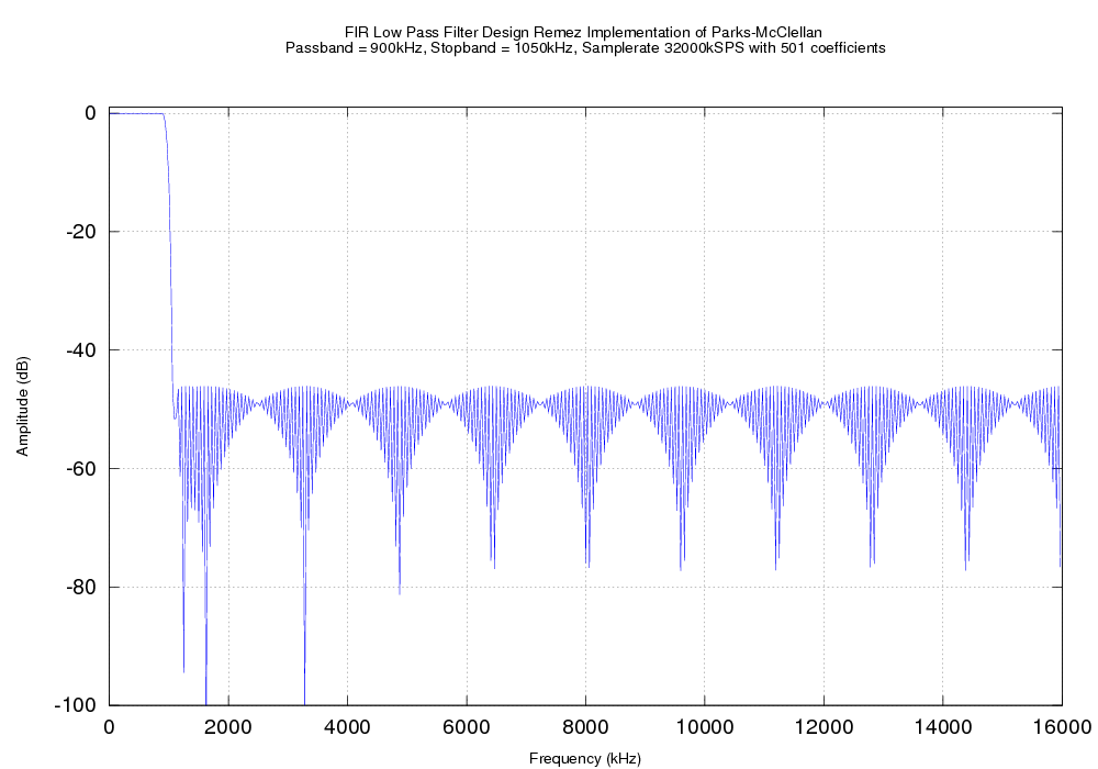
- FIR : 501 taps, fixed /16 decimation, passband 900kHz, stopband 1050kHz. Diagram shows filter design.
- The FPGA
 logic implements a generic 501 tap FIR filter on each channel, many other filter characteristics are possible, please contact D‑TACQ with your requirement. Or try it out for yourself using this Gnu-Octave script to generate the coefficients and plot the characteristic.
Download the precompiled set of FIR filters
Computed FIR response
Results
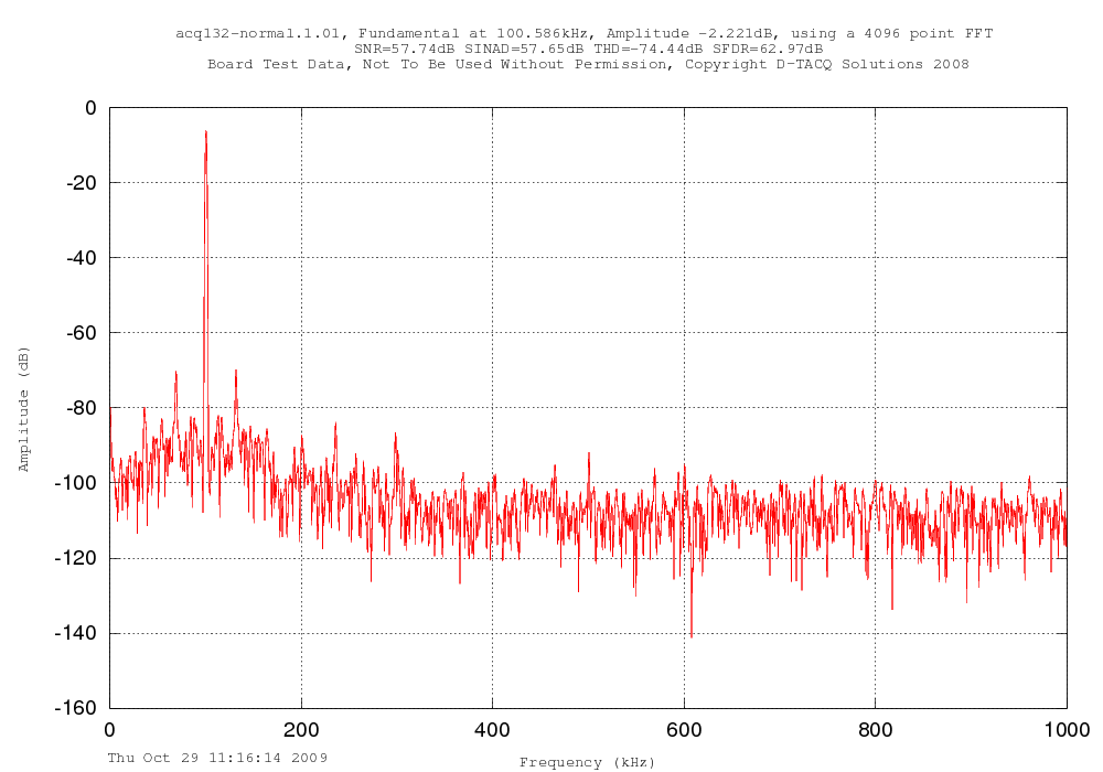
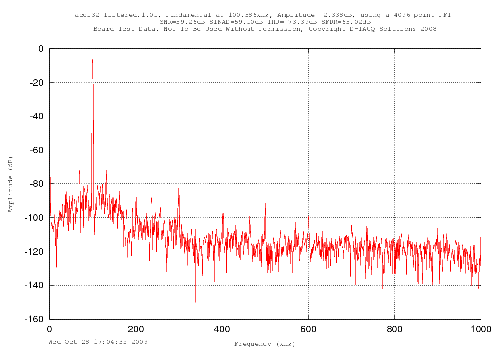
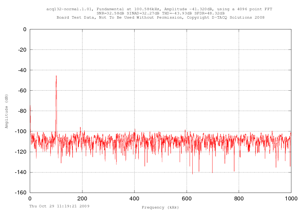
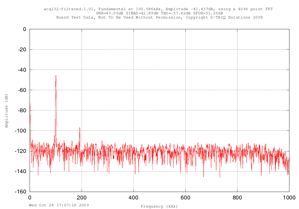
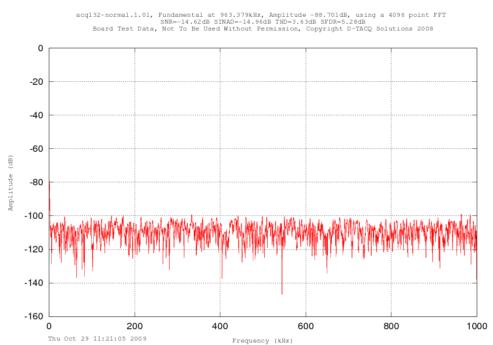
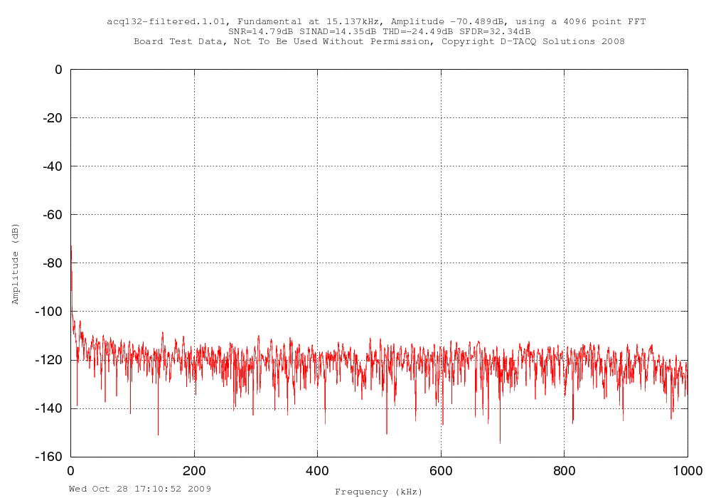
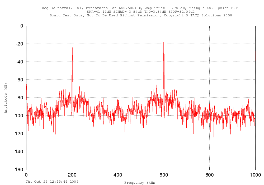
Comparing data with and without filter shows that significant processing gain is achieved, and aliased harmonics are eliminated.
| Signal |
Without Filter |
With Filter |
100kHz
10V |
 |
 |
100kHz
100mV |
 |
 |
| no signal |
 |
 |
600kHz
Square
Wave |
 |
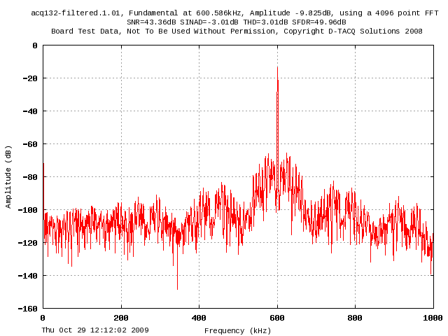 |
The unfiltered square wave input shows the 3rd harmonic (1800kHz, reflected at 200kHz) as expected; in the FIR filtered case, the 3rd harmonic is in the stop band and is completely eliminated.